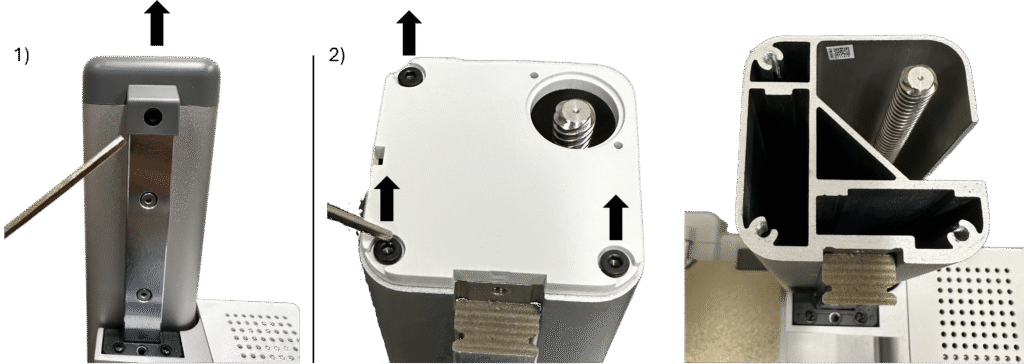
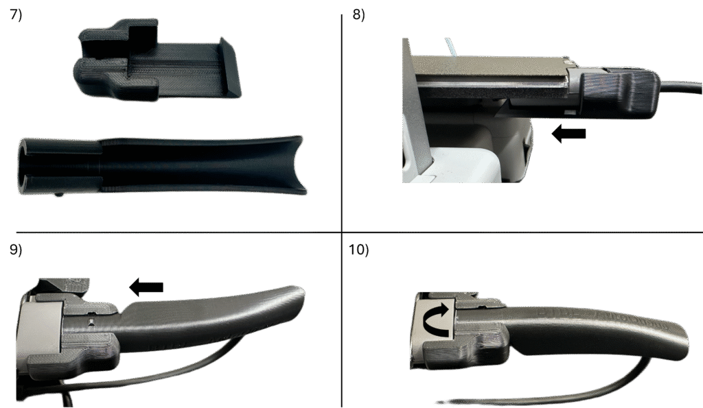
1. Using the 2.5mm Allen Wrench, remove the front facing screw from the top of the z-axis cover and remove the gray cover.
2. Using the 2.5mm Allen Wrench, remove the three screws from the top of the white z-axis cover.
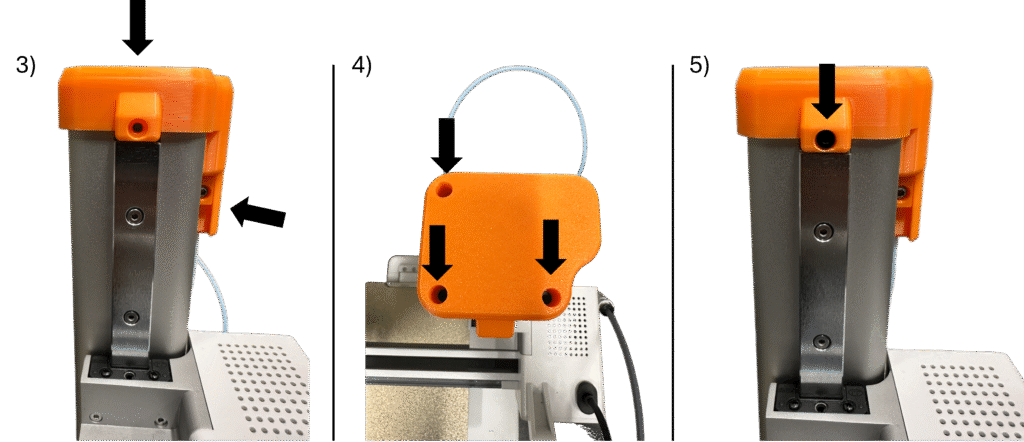
3. Install the Top Assembly in place of the z-axis cover in the orientation shown. The Top Slider channel should sit just outside the slot on the right side of the z-axis.
4. Reinstall the three stock screws from the white z-axis cover on the top of the Top Assembly.
5. Reinstall the stock screw from the gray z-axis cover on the front of the Top Assembly.
6. Align the Sling Hook assembly directly underneath the wiper on the back of the printer bed. It should snap into place. Ensure that it works correctly by removing the build plate from the printer bed – once removed, the hooks on the Sling Hook Catch should rotate above the build surface.
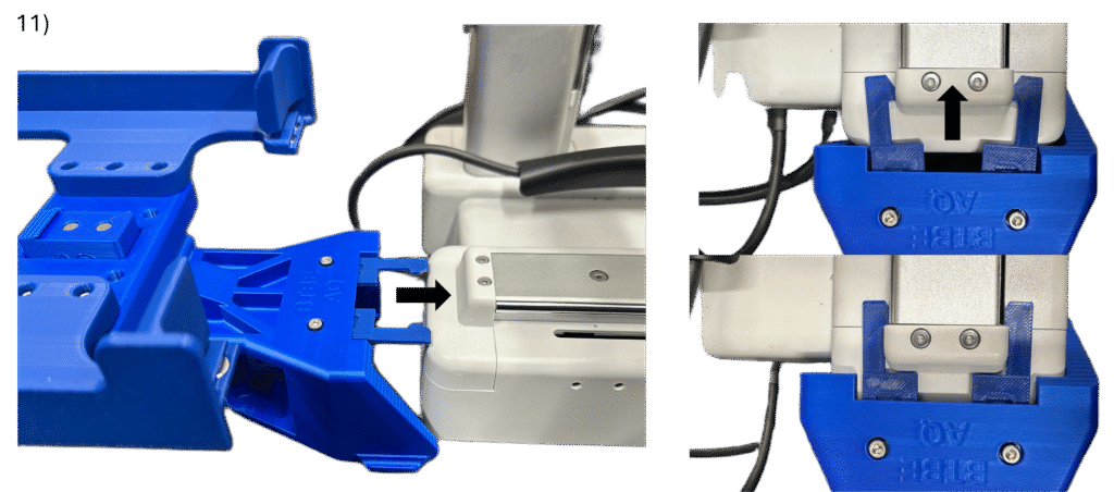
7. Locate the Cable Guard Lock and the Cable Guard.
8. Insert the Cable Guard Lock around the cord coming off of the printer bed and slide towards the printer bed as far as it will go, interlocking as shown.
9. Insert the Cable Guard into the Cable Guard Lock such that the notch on the Cable Guard is vertically positioned in the free space.
10. Rotate the Cable Guard clockwise 90 degrees such that the notch on the Cable Guard slides into the slot in the Cable Guard Lock.
11. Manually move the printer bed as far forward toward the front of the printer as it will go. Align the Back Assembly with the y-axis rail on the backside of the machine as shown. Push the Back Assembly straight onto the printer to install, allowing the Back Latch to latch onto the cap on the back of the y-axis rail. Ensure that the Back Assembly sits flat in-line with the printer (it may or may not need pushed down on the back, and it may or may not audibly click into place)
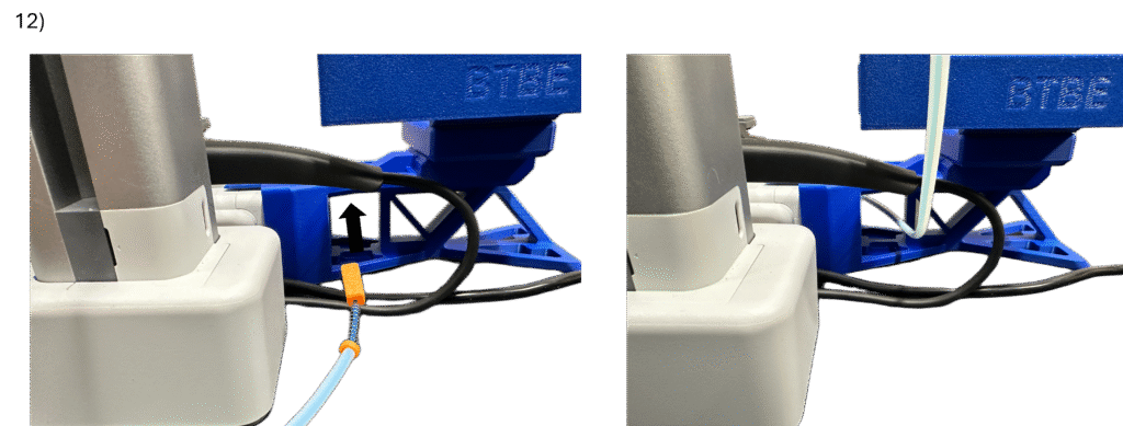
12. Manually move the printer bed as far backwards (towards the back assembly) as possible. Feed the Tension Block end of the Cable through two things to the other side of the printer: A) the wire being secured by the Cable Guard, and B) the rectangular opening through the side of the Back Assembly.
13.) Insert the Tension Block into the front channel in the Front Base as shown. Pop the head of the Tensioner Screw out of the hole in the side of the front channel onto the side of the Front Base and push it as far forward as it will go.
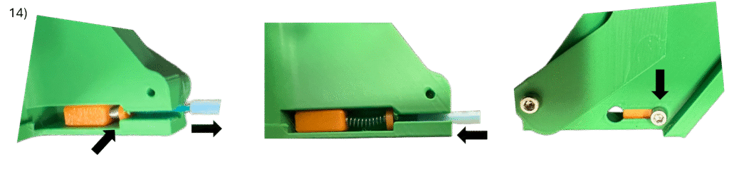
14. Insert the Cable Spring and Front Washer into the front channel. Similar to setting up this assembly inside the Tensioner Tool, pull the PTFE tube (compressing the spring) and allow the Cable to slide into the front channel. Then, insert the PTFE tube into the in-line hole in the Front Base and push it in as far as it will go (about halfway into the hole as shown). When installed correctly, the head of the Tensioner Screw should sit at the far end of the front channel as shown.
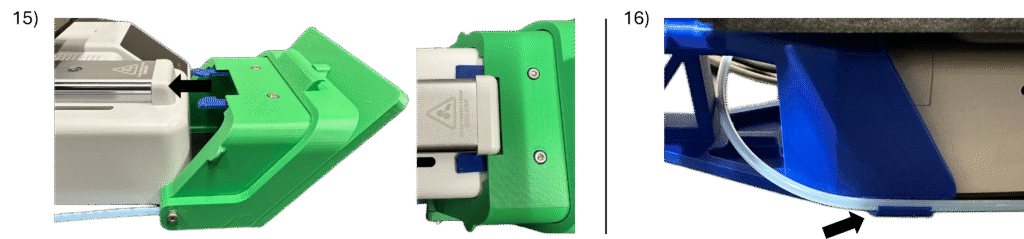
15. Manually move the printer bed as far backwards towards the back of the printer as it will go. Align the Front Assembly with the y-axis rail on the frontside of the machine as shown. Push the Front Assembly straight onto the printer to install, allowing the Front Latch to latch onto the cap on the front of the y-axis rail. Ensure that the Front Assembly sits flat in-line with the printer (it may or may not need pushed down on the front, and it may or may not audibly click into place).
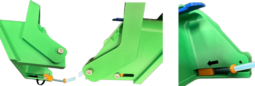
16. Clip the PTFE Tubing into the holder on the side of the Back Assembly.
17. Test the Front Catch actuation system by manually pressing the Top Slider upwards into the top channel. This should cause the Front Catch to rotate and lift upward. If it does not, please revisit the Top Assembly documentation.
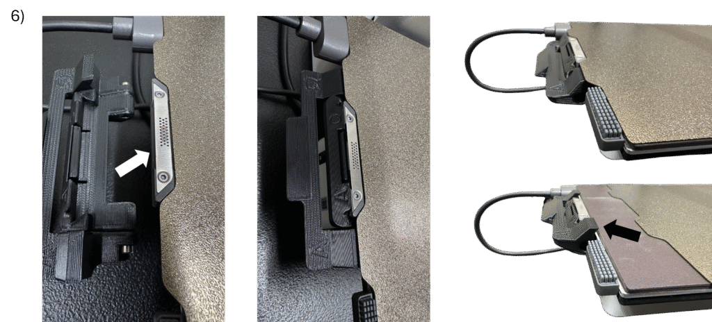
18. Insert assembled build plates into the Back Assembly of the AutoQueue. When replacing a build plate directly onto the print bed, be sure to push down the Sling Hook Catch before aligning the build plate on the print bed, ensuring that the Sling Hook Catch sits underneath the build plate during normal use.
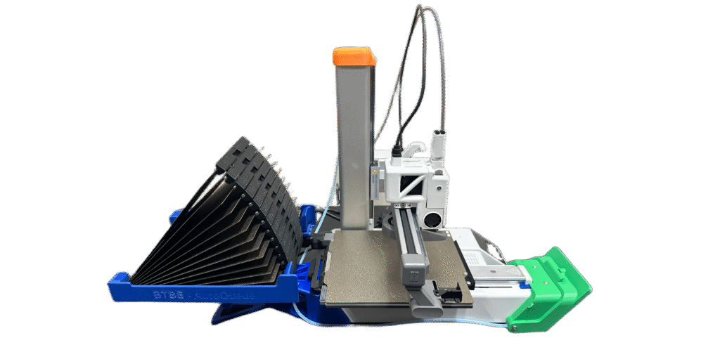
Printer Assembly Complete!
Now its time to use the Queue Creator. Click here for a guide.