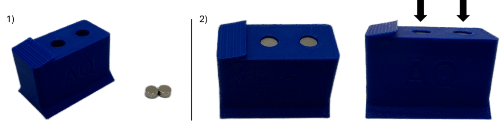
1. Locate the Back Snag and two of the six Small magnets.
2. Press the magnets into their respective holes on the top of the Back Snag, ensuring a snug fit. The magnets should sit just below the top surface of the Back Snag. It may be useful to turn the Back Snag upside down and press the magnets in by using the edge of a hard table.
Note: The local orientation of the magnets does not matter, as long as they both face the same direction.
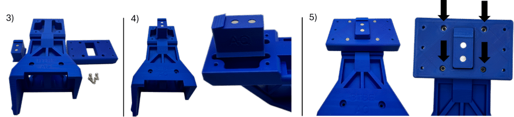
3. Locate the Back Housing, Back Riser, Bag Snag Assembly, and four of the 18 Assembly Screws.
4. Place the Back Snag Assembly on top of the back-end of the Back Housing, ensuring that the ramp on the top of the Back Snag is pointed towards the back-end of the Back Housing as shown.
5. Place the Back Riser on top of the Back Housing around the Back Snag in the orientation shown. The side of the Back Riser facing “up” should be the side with centralized holes large enough to insert Assembly Screws. Insert the four Assembly screws as shown and slowly fully tighten using the 3mm Allen Wrench.
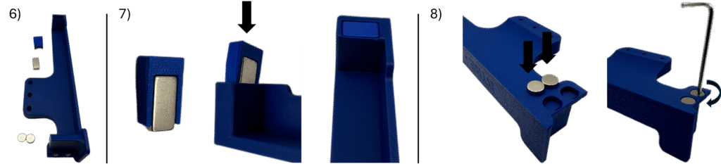
6. Locate the Back Arm – Left, one Large Magnet, two of the Medium Magnets, and one of the Magnet Wedges.
7. Insert the Large Magnet into the Magnet Wedge, and then insert into the open rectangular cutout on the back of the Back Arm – Left such that internally the magnet faces towards the center of the part.
8. Insert the two Medium Magnets into their respective holes on the underside of the Back Arm – Left, ensuring a snug fit. This may be difficult, as the fit is tight to ensure the magnets stay in place – it may be useful to use the edge of a table, or use an Allen Wrench to help force the magnet into position.
Note: The local orientation of the magnets does not matter, as long as they both face the same direction.
Once complete, repeat steps 6-8 for the Back Arm – Right.
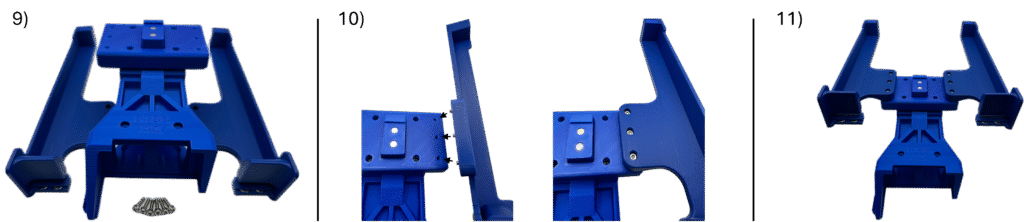
9. Locate the Back Arms Left/Right assemblies, the Back Housing assembly, and six of the 18 Assembly Screws.
10. Insert three Assembly Screws into their respective holes on the Back Arm – Right, align with the holes on the right side of the Back Riser on the Back Assembly, and slowly fully tighten using the 3mm Allen Wrench.
11. Repeat step 10 for the Back Arm – Left.
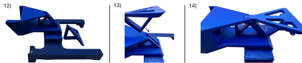
12. Turn the Back Assembly upside-down and locate the Back Support.
13. Align the Back Support with the slot in the Back Housing as shown.
14. Slide the Back Support into the slot in the Back Housing such that the flat faces align.
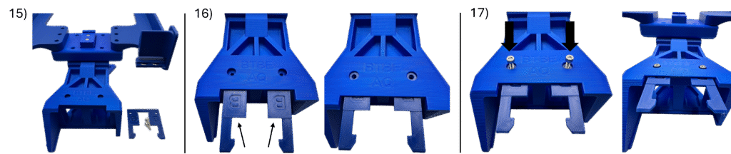
15. Locate the Back Assembly, Back Latch, and two of the 18 Assembly Screws.
16. Insert the Back Latch into the front of the Back Housing Assembly, lining up the holes in the Back Latch with the holes on top of the Back Housing Assembly. At this point, double check to confirm that this is the Back Latch (this part has inscribed “B”s on top, as opposed to the Front Latch which has inscribed “F”s on top) and that the Back Latch is in the correct orientation (the inscribed “B”s should be facing upward)
17. Insert the Assembly Screws and slowly tighten until secure.
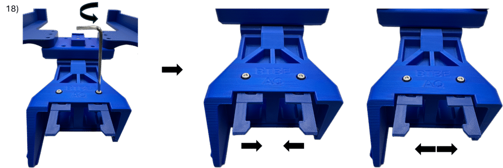
18. With the Assembly Screws fully secure, rotate them 1/8th of a turn counterclockwise to barely unscrew them, giving them a little bit of wiggle room. This should allow the Back Latch to slightly open if manually forced open.
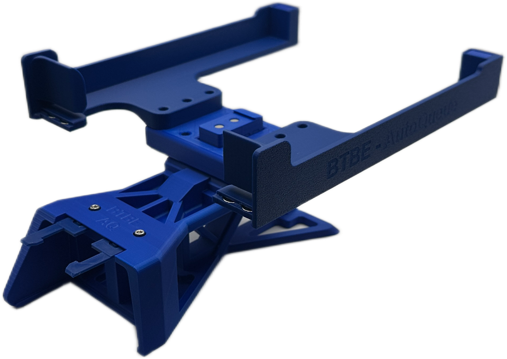
Back Assembly Complete!